Milling Machine
Prior to using the milling machine, you must set up a time on the calendar. You may need to open this on a computer rather than mobile device.
First thing’s first: Get trained on the milling machine. The machine is for classroom or research uses only. So you must be working on a project for your class or for some research project.
- Check out the calendar and pick 2 hours of available time. You must pick two dates (primary and secondary) 7 days in advanced from the date you requesting to use the machine.
- Email ELEG Help at eleghelp@uark.edu saying you’d like to get trained on the machine citing the time/date you have chosen in addition to your secondary date.
- Once you’ve received an email verifying your reservation, you will wait outside ENGR 110 for for training on the agreed upon date .
Senior Design will have their own training as specified by the GTA.
Now that your trained, check out the board requirements page when working on your own design.
If you’re new to the milling machine, please make sure you schedule for training (see above).
Rules:
- EYE protection is required when using this machine
- Always schedule a time to use the milling machine
- Adhere to the milling machine tutorial (below) for all boards you mill, so you don’t make mistakes
- NEVER touch any of the tools in the tool holder
- Be mindful of what I am doing when in CNC mode manually moving the spindle back and forth
- Email eleghelp@uark.edu if there is an issue
- Keep to the depths stated in the tutorial and not change any tool settings such as feed and plunge rates
- Check designs using the PHCNC demo before using the milling machine
When you finish training, you will sign a usage agreement stating you will follow the rules. If you break a rule, you will lose access and need to be retrained.
*NOTE: Training is self led instruction. A minimum of 2 people are to be in the milling room at any time. Please contact your lab instructor or eleghelp@uark.edu with any questions.*
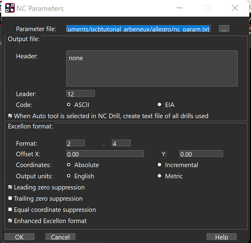
In PCB editor/design, go to “Manufacture” -> NC -> “NC Parameters”. Match your settings to these below. Click close.
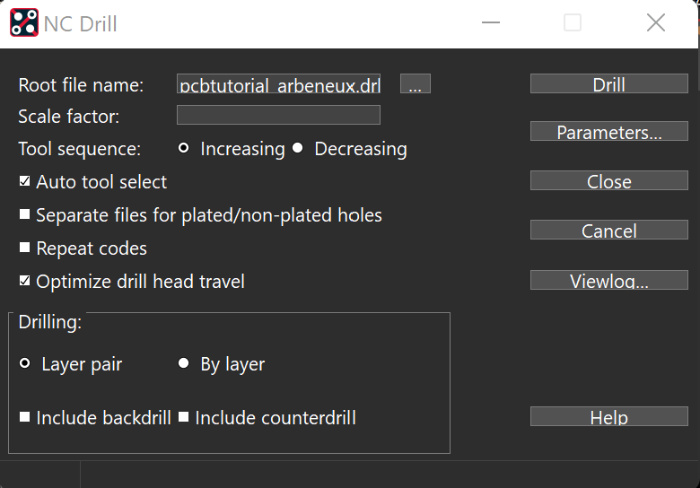
In PCB editor/design, go to “Manufacture” -> NC -> “NC Drill”. Match your settings to these below. Click drill. This will generate a drill file in the same location your artwork/gerber files are generated.
Gerber Files
Your board files need to be in GERBER format. You will need 3 to 4 separate files depending on if your using 1 or 2 layers.
Needed files are: TOP.art, BOTTOM.art, OUTLINE.art, and DRILL.art
-please see the cadence PCB tutorial to see instructions.
DRILL HOLES
The milling machine is equipped with several drills to create your board. It would be wise to make your board with specs provided below so you don’t run into problems. See the Generate a Drill file
Sizes available
- .5mm+ router –
- .0315”/.8mm+ router –this is the router bit and allows you to drill holes equal and bigger than itself
- .0216”/.55mm drill bit
- .0177”/.45mm drill bit
- .0157”/.4mm drill bit
Line WIDTH
Try to make your line width at least 15 mils. The machine can do smaller traces, but we’ve had more consistent results with 15 mils. Small pads will limit this of course. This is done in “SETUP” -> “Constraints” -> PHYSICAL in PCB Editor/design. See the Milling machine manual for spacing and width details for higher current and voltages.
LIMITATIONS of the Milling machine
The milling machine has no solder mask abilities. This is the green solder resist that coats the board except where the parts are soldered.
The milling machine does not tin pads. Tinning is a layer of solder placed on pads to make it easier to place parts (mostly surface mounts parts)
Check out the above circuit. The silkscreen is the white letters and shapes to help indicate the orientation and identification of parts for placement.
The solder mask is the green parts and resists solder so you don’t accidentally solder onto another area
As you can see the pads are a silver color. This means there is a layer of solder already placed on the board. If there wasn’t you would see copper.
The circuit above was done with our milling machine. Your board starts as a piece of copper and that copper is etched away to create pads and traces. As you can see there are parts where the copper has been removed quite a bit.
The process of rubout removes residual copper to make it easier to solder parts.
The smaller the pads, the more difficult to solder. So make your pads as large as possible but this ofcourse is limited to the parts you use.
Q: What happens if I break a rule?
A: When you finish training, you will sign a usage agreement stating you will follow the rules. If you break a rule, you will lose access and need to be retrained.
Q: I need to use the milling machine. how do i do this?
A: Check out the training section above.
Q: How long does training take?
A: Training takes 2 hour to complete. So allot that much time.
Q: Now that I’m trained, can I use the milling machine whenever i want?
A: Once you have trained on the machine, you still need to reserve time using the calendar and emailing the TA in charge
A: How long does it take to mill a board?
A: This depends on several factors. (size, pad complexity, number of parts, etc). A good rule is 15 minutes per square inch for single sided boards. 30 minutes/sq in for double sided board. It is always better to overbook your time.
Q: Can I install the cam software on my personal computer?
A: Yes you can. A demo version is available to download with limited abilities such as being only able to import Gerber files.
Q: I need to use thicker copper, how do i do this?
A: For senior design or your research project, you will need to purchase your specific copper using your designated funds. Now email eleghelp@uark.edu so we can test depths for your copper. When you schedule a time to mill your board, make sure you email eleghelp@uark.edu as well so someone can be there to ensure things go well.